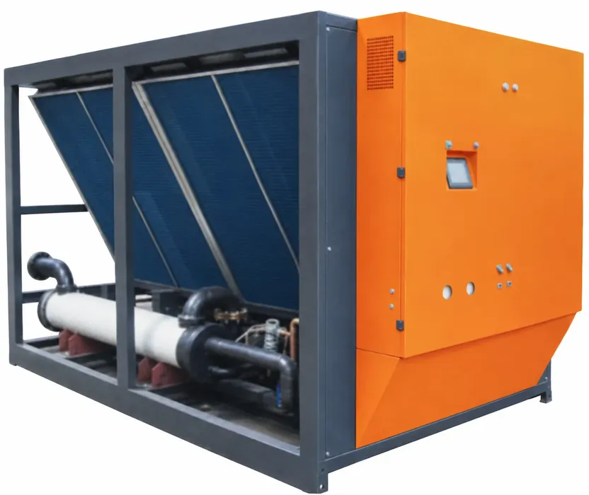

When adding an injection molding machine to a shared chilled-water loop, check both the cooling capacity available at the required operating conditions and the water flow the new branch can receive while the existing machines run. The loop needs enough cooling for the combined load, with margin for variation, and enough flow at the new and existing branches.
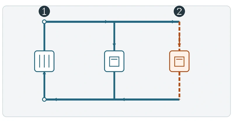
Measure the shared-loop heat load
Record which presses and auxiliaries run together today. List the busiest combinations you expect after expansion separately. Measure flow and supply and return temperatures across the same circuit, at the same time under stable conditions. A mold temperature controller with a separate secondary loop contributes the heat it transfers to the shared loop; keep its secondary flow separate from the shared-loop reading.
For stable plain-water conditions at the same measurement boundary:
Heat load Q (kW) ≈ 0.0697 × flow (L/min) × temperature difference (°C)
In a hypothetical shared loop, 120 L/min of water with a 5°C return-to-supply temperature difference carries approximately 41.8 kW. If the new machine and its associated loads add 12 kW to that same loop at the same time, the combined load is approximately 53.8 kW. A chiller able to deliver 55 kW at the required leaving-water temperature and condenser conditions would then have about 1.2 kW of thermal margin. Compare that margin with load swings and the uncertainty in your measurements and estimates.
For the added duty, ask for the estimated heat the new mold, press and auxiliaries will transfer into the shared loop at the planned cycle. Check different simultaneous operating cases and any different supply-temperature requirement. The coefficient above applies to the stated water conditions. For glycol mixtures, use fluid properties at the actual concentration and temperature. Do not combine flow and temperature difference from different boundaries or operating times.
For rated kW, refrigeration tons and the conditions behind a rating, see industrial chiller cooling capacity.
Check pressure and flow independently
Obtain the equipment pressure drop at its required flow, then add hose, valve and fitting losses at that same flow. Compare the result with the supply-to-return differential pressure available at the proposed connection at the expected simultaneous flows. Check the pump curve and system operating point, minimum chiller flow and the effect on existing branches.
In the same hypothetical expansion, suppose the equipment needs 35 L/min and has a 48 kPa pressure drop at that flow. Hoses and valves add 22 kPa, so the branch requires 70 kPa at 35 L/min. If the system model predicts only 55 kPa at that connection with the new branch at 35 L/min and the existing branches at their required flows, the proposed operating point falls 15 kPa short. Use the pump curve and branch losses to assess what flow the system can supply, then verify it under simultaneous production.
After installation, verify the new and affected existing branch flows while they operate together. If shared-loop supply temperature rises under combined load, compare the measured heat load with capacity at those conditions and investigate chiller operation. If temperature is suitable but a branch lacks flow, investigate distribution and restrictions. If both deteriorate, log temperatures, flow and chiller state together before choosing an upgrade.
What to ask the supplier to confirm
| Check | Required at the proposed duty | Available at the same duty | Margin or shortfall |
|---|---|---|---|
| Cooling capacity (kW) | Existing measured load + estimated new load: ___ | Supplier rating at the same water and condenser conditions: ___ | ___ kW |
| New connection pressure difference (kPa) | Device and branch losses at target flow: ___ | Predicted site differential, checked against the pump curve: ___ | ___ kPa |
| Flow at new and affected branches (L/min per branch) | Required flow at each branch: ___ | Predicted before installation, measured at commissioning: ___ | ___ L/min per branch |
Send the completed sheet with the loop fluid and concentration, measurement locations, operating cases, chiller minimum evaporator flow, pump model or curve and relevant piping. For an air-cooled condenser, include entering air temperature; for a water-cooled condenser, include entering water temperature and flow. Record independent secondary circuits separately.
For heat rejection choices, see air-cooled vs water-cooled chillers for plastics. If the existing system cannot meet the proposed duty, share the circuit readings and operating conditions when discussing an upgrade.